Manufacturing experts in pulp molded products:EAMC,China pulp molding machines manufacturer, supplier, factory. EAMC full-automatic molded fiber (pulp) production line.
EAMC equipment and key components have obtained a series of Chinese invention patents, United States invention patents, and EU invention patents
Specification
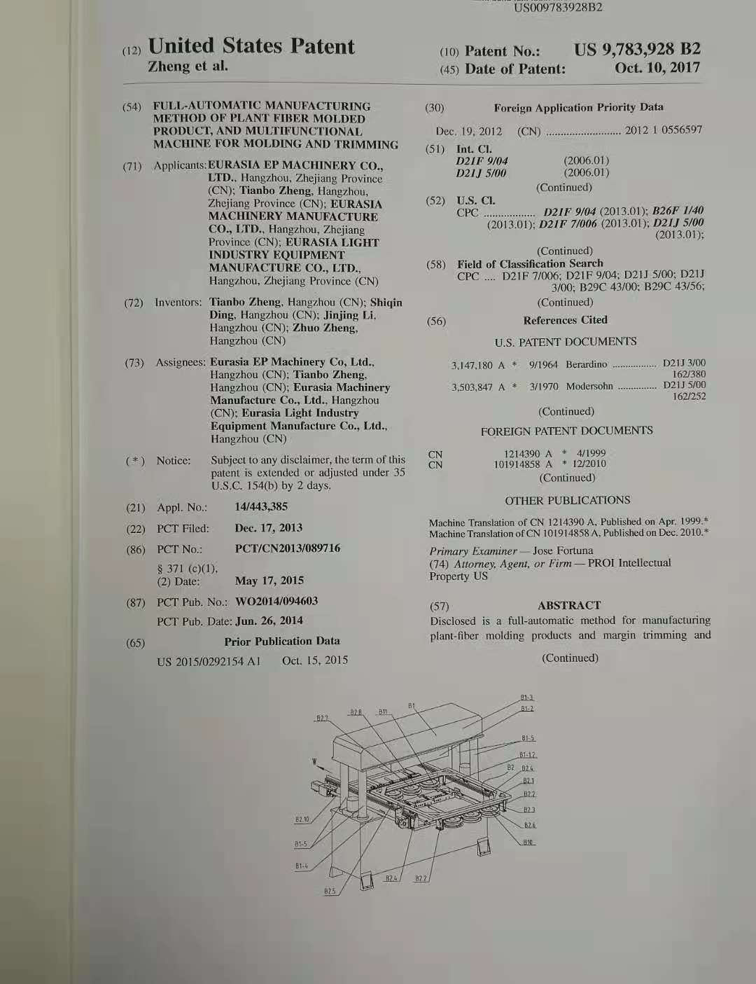
A Full-automatic method for manufacturing plant-fiber molding products and plant-fiber MARGIN trimming molding machine
Background of the invention
Technical Field
The present invention relates to a method and device for making plant fiber (referred to as plant fiber hereinafter) products including pulps by pressing & molding; for manufacturing plant-fiber molding products (or pulp molding products, hereinafter collectively referred to as plant-fiber molding products), especially for manufacturing non-planar paper products; such as plant fiber tableware, plant fiber trays, industrial plant-fiber shock pads, packaging boxes and trays, non-planar three-dimensional decorative plant-fiber wall panels (or referred to as three-dimensional plant fiber wallpapers or three-dimensional pulp molding wallpapers) and all plant-fiber molding products.
Description of Related Art
The process for making plant-fiber molding products is as follows: plant fibers are made into wet semifinished products by means of a suck-filter forming device after suck-filter forming, which will be alternatively fed into hot-press molds of the left hot press mold solidifing device and the right hot press mold solidifing device on both sides of the suck-filter forming device after being heated to a certain temperature for clamping and hot-press mold drying and solidifying, thus making plant-fiber molding products in various shapes. This is the dual hot press mold solidifing device mode of the method for manufacturing plant-fiber molding products.
The present invention is explained by taking the dual hot press mold solidifing device mode of the method for manufacturing plant-fiber molding products as an example. There is a common three-station full-automatic plant-fiber molding machine, comprising a forming & solidifying top rack, a forming & solidifying low rack, a rod for connecting the forming & solidifying top rack and the forming & solidifying low rack, a suck-filter forming device (forming station) arranged between the forming & solidifying low rack, a left hot press mold solidifing device (or referred to as the left solidifying station) with the left hot-press top & low molds and a right hot press mold solidifing device (or referred to as the right solidifying station) with the right hot-press top and low molds on both sides of the suck-filter forming device, wherein a wet semifinished product transfer device is arranged above the suck-filter forming device and fixed on the forming & solidifying top rack with its transfer mold clamp moveable up and down; furthermore, the left and right hot-press low molds alternatively move below the transfer device respectively along the horizontal track of the hot-press low mold driven by power so as to receive the wet semifinished products transferred from such transfer device. After the wet semifinished products are transferred into the left or right hot-pressure low mold and return just below the left or right hot-pressure top mold from the transfer mold, the left hot-press top mold closes with the left hot-pressure low mold downward and implements the hot press mold solidifying for the wet semifinished products (or the right hot-press top mold closes with the right hot-pressure low mold downward and implements the hot press mold solidifying for the wet semifinished products driven by the external force, such as moving the tank or cylinder from the right hot-press top mold) driven by the external force (moving the tank or cylinder from the left hot-press top mold) until the wet semifinished products are dried and solidified to remove the product by mold opening. Repeat the above steps again and again. This is the full-automatic plant fiber (including pulp) molding machine by means of the dual hot press mold solidifing device mode, consisting of “the left hot press mold solidifing device, suck-filter forming device and the right hot press mold solidifing device”. For example, the plant fiber molding (including pulp molding) machine disclosed in CN patents 03209714.X, ZL201020283075.2, ZL 201010246235.0, ZL201020283085.6 and other related patents are such typical production units.
The wet semifinished products are dried and solidified to remove the products by mold opening in two ways: 1. the full-automatic pulp molding machine is connected with the left and right conveyor belts on the left hot-press low mold (including a mold mounting plate for mounting the left hot-press low mold) and the right hot-press low mold (including a mold mounting plate for mounting the right hot-press low mold). After the wet semifinished products are heated, dried and solidified, the left hot-press top mold opens and absorbs the products to move upward while the left hot-press low mold moves just below the transfer mold, the left conveyor belt is just below the left hot-press top mold as the left hot-press low mold moves to the right and the products absorbed by the left hot-press top mold fall onto the left conveyor belt; afterward, the left conveyor belt also returns to the original position and turns to deliver the products out of the machine with the left hot-press low mold returning to the original position. Similarly, the right hot-press top mold opens and absorbs the products to move upward while the left conveyor belt is just below the right hot-press top mold as the right hot-press low mold moves to the left just below the transfer mold clamp and the products absorbed by the right hot-press top mold fall onto the right conveyor belt; afterward, the right conveyor belt delivers the products out of the machine with the right hot-press low mold returning to the original position. Therefore, the left and right conveyor belts deliver the product out by wet semifinished product forming and hot press mold solidifying. 2. The left and right conveyor belts are replaced with the left plate and the right plate respectively, wherein the products absorbed by the left and right hot-press top molds are blown on the left and right plates respectively. The products are removed from the left and right plates by artificial collection; the left plate with products can be turned to the left at a certain angle so that the products slide out from the left plate or the right plate with products can be turned to the right at a certain angle so that the products slide out from the right plate.
Thus, the dried and solidified products alternatively fall from the left and right hot-pressure top molds and are delivered out from the left conveyor belt (the left plate) or the right conveyor belt (the right plate).
In the prior art, there is a single-side hot press mold solidifing production device arranged on the left or right (either) side of the suck-filter forming device with the same production process as described above. However, one suck-filter forming device is provided with one hot press mold solidifing device, which is known as the single hot press mold solidifing device mode of the method for manufacturing plant-fiber molding products. Moreover, there is a full-automatic plant fiber molding machine with a multi-function auxiliary device to eliminate the mold dripping of the automatic molding machine. Therefore, the process for making plant fiber molding products (including pulp molding products) includes two main processes and functions, namely wet semifinished product forming and hot press mold solidifying in the prior art.
For various reasons, the actual edge of the plant fiber molding products produced by forming and mold solidifying often fails to achieve the design requirements. In order to achieve the precise shape or profile of products, some margin trimming allowances are allowed for the edge of the pre-margin trimmed products and the excess is removed by margin trimming, thus realizing the required process and method by cutting the products into the required shapes. This process and method is known as margin trimming (processes such as removal of extra product edges, product cutting, slitting of single products in integrated products, product punching, product puncturing, cut marks or indentations left on products are all classified as margin trimming).
Until now, all international methods and devices for making and producing plant fiber molding products are designed so that wet semifinished product forming and hot press mold solidifying can be continuously performed on the same device; scattered products cannot be determined in a fixed position after they slide out from the conveyor belt or the left and right plates via hot press mold solidifying. The rim of plant fiber molding products produced has always some rough edges, with which the products are artificially collected and margin trimmed by a margin trimming machine. A method and device cannot be yet achieved to continuously perform the processes below: from wet semifinished product forming to hot press mold solidifying and to scrap removal. As a result, intact, margin trimmed and high-quality products cannot be produced on the same machine.
BRIEF SUMMARY OF THE INVENTION
The purpose of the present invention is, by overcoming the above shortcomings in the prior art, to provide a full-automatic method for manufacturing plant-fiber molding products and full-automatic plant-fiber molding, mold solidifying and margin trimming machine; the method and the molding machine have three functions: wet semifinished product forming, hot press mold solidifying and automatic margin trimming, with the realization of advantages including high degree of automation, good quality of products and high production efficiency.
The present invention provides the following technical solutions: the full-automatic method for manufacturing plant-fiber molding products with the process is provided, wherein: pulps are continuously made into wet semifinished products by means of a suck-filter forming device, which will be alternatively fed into hot-press molds of the left hot press mold solidifing device and the right hot press mold solidifing device after being heated to a certain temperature for hot-press drying and solidifying, characterized in that: the dried and solidified products fall into the left positioning collection tray of the left positioning collection device and the right positioning collection tray of the right positioning collection device respectively from the left hot-press top mold and the right hot-press top mold, and are positioned therein, to achieve the purpose of fixing the products in a specific position for transfer and ensure the transfer accuracy of the products to be margin trimmed;
The left positioning collection device delivers the dried and solidified products to be margin trimmed to the left transition station and the right positioning collection device delivers the dried and solidified products to be margin trimmed to the right transition station; the products to be margin trimmed are transferred to the position to be margin trimmed of the margin trimming device by the transfer device positioned on the left transition station and the right transition station, and then the margin trimming device withdraws the products to be margin trimmed from the position to be margin trimmed, delivers them to the margin trimming position for margin trimming, and then delivers the margin trimmed products to the completion position and expels the margin trimmed scrap from the margin trimming position; thus the full-automatic process for manufacturing plant fiber molding products operates continuously starting from making pulps into wet semifinished products by suck-filter forming to delivering the products to the completion position after margin trimming.
The left discharge sucker kit in the transfer device withdraws and absorbs the products to be margin trimmed in the left positioning collection tray on the left transition station through vacuum absorption, delivers such products to the left product receiving station along the left discharge horizontal track, and then to the left storage flipper for realization of flipping the products to be margin trimmed or directly to the positioning tray to be margin trimmed in the left transport vehicle on the left product receiving station; the right discharge sucker kit in the transfer device withdraws and absorbs the products to be margin trimmed in the right positioning collection tray on the right transition station through vacuum absorption, delivers such products to the right product receiving station along the right discharge horizontal track, and then to the right storage flipper for realization of flipping the products to be margin trimmed or directly to the positioning tray to be margin trimmed in the right transport vehicle on the right product receiving station, so that the products to be margin trimmed are re-positioned in the positioning tray to be margin trimmed, thus achieving the transfer of the products to be margin trimmed from front to back.
The left transport vehicle in the transfer device receives the products to be margin trimmed on the left product receiving station and delivers them to the position to be margin trimmed; the right transport vehicle in the transfer device receives the products to be margin trimmed on the right product receiving station and delivers them to the position to be margin trimmed, namely the left and right transport vehicles alternatively deliver the received products to be margin trimmed to the position to be margin trimmed.
The margin trimming device withdraws the products to be margin trimmed from the position to be margin trimmed, delivers them to the margin trimming position for margin trimming, and then delivers the margin trimmed products to the completion position.
Margin trimming molds are mounted in the margin trimming & clamping mechanism of the margin trimming device, comprising a margin trimming top mold and a margin trimming low mold, wherein a positioning block is arranged on the margin trimming low mold to fit the shape of products for determining the product position on the margin trimming low mold.
The margin trimming device delivers the products from the position to be margin trimmed to the margin trimming position, and then to the completion position, of which the process is completed through product withdrawing and absorption with a margin trimming sucker kit.
The margin trimming sucker kit is divided into two spaced kits, namely the front-row margin trimming sucker kit and the back-row margin trimming sucker kit, wherein the front-row margin trimming sucker kit absorbs the products to be margin trimmed on the position to be margin trimmed placed on the front side of the margin trimming mold and transfers them onto the positioning block of the margin trimming low mold, the back-row margin trimming sucker kit absorbs the margin trimmed products on the positioning block of the margin trimming low mold and delivers them out of the margin trimming mold, and then places them on the completion position on the back side of the margin trimming mold.
The margin trimming device performs the process as below:
1) the front-row margin trimming sucker kit (on top of the position to be margin trimmed) moves down to absorb the products to be margin trimmed and moves up to return its original position, while the back-row margin trimming sucker kit (on top of the positioning block of the margin trimming low mold) moves down to absorb the margin trimmed products and moves up to return its original position;
2) the front-row margin trimming sucker kit and the back-row margin trimming sucker kit move backward horizontally with the products withdrawn, the scrap removal mechanism expels the margin trimmed scrap from the margin trimming position;
3) after moving backward horizontally to some distance, the front-row margin trimming sucker kit and the back-row margin trimming sucker kit release the products withdrawn respectively, making the products to be margin trimmed fall onto the margin trimming position while the margin trimmed products onto the completion position; the front-row margin trimming sucker kit and the back-row margin trimming sucker kit move forward horizontally & simultaneously, and then stop horizontal movement when the spaced front-row margin trimming sucker kit and the back-row margin trimming sucker kit are in a position on the front and back side of the margin trimming mold respectively;
4) the margin trimming top mold moves downward from the margin trimming mold to clamp with the margin trimming low mold and remove the rough edges of the products to be margin trimmed; and then the margin trimming top mold moves upward from the margin trimming mold to open the mold;
5) the front-row margin trimming sucker kit and the back-row margin trimming sucker kit continue to move forward horizontally until the front-row margin trimming sucker kit and the back-row margin trimming sucker kit reach to the top of the position to be margin trimmed and the margin trimming position respectively;
6) the front-row margin trimming sucker kit and the back-row margin trimming sucker kit moves down respectively or simultaneously to absorb the products to be margin trimmed and the margin trimmed products and then moves up to return its original position;
then repeat steps 2) to 6) again and again.
A piece or set of scrap blowing rods are adopted to move back and forth make horizontally with the front-row margin trimming sucker kit and the back-row margin trimming sucker kit, wherein the scrap blowing rod blows or moves and blows to blow the scrap off the margin trimming low mold within a period of time when the back-row margin trimming sucker kit absorbs and moves the margin trimmed products to the completion position, without affecting the positioning of the next products to be margin trimmed on the positioning block.
The scrap sucker kit absorbs the margin trimmed scrap from the margin trimming mold and then removes it out of the margin trimming mold without affecting the positioning of the next products to be margin trimmed on the positioning block.
The full-automatic plant-fiber molding, mold solidifying and margin trimming machine, includes a forming and solidifying device A for making products to be margin trimmed, a transfer device C for transferring the products to be margin trimmed to the position to be margin trimmed of the margin trimming device and a margin trimming device B for margin trimming of the products to be margin trimmed.
The forming and solidifying device comprises a suck-filter forming device A2, a transfer device A7 for withdrawing wet semifinished products from the suck-filter forming device, a left hot press mold solidifing device A3 and a right hot press mold solidifing device A4 for receiving, heating and drying wet semifinished products respectively, a left positioning collection device A5 for receiving the products to be margin trimmed in the left hot press mold solidifing device and delivering them to the left transition station, and a right positioning collection device A6 for receiving the products to be margin trimmed in the right hot press mold solidifing device and delivering them to the right transition station.
The left hot press mold solidifing device and the right hot press mold solidifing device are symmetrically arranged on the left and right sides of the suck-filter forming device; the left positioning collection device is arranged on the left side of the left hot press mold solidifing device and fixed onto the mounting plate of the left hot-press low mold together with the left hot-press low mold in such device, wherein the mounting plate can move to the left and right horizontally through a slider to position on the horizontal track (A8) of the hot-press low mold; the right positioning collection device is arranged on the right side of the right hot press mold solidifing device and fixed onto the mounting plate of the right hot-press low mold together with the right hot-press low mold in such device, wherein the mounting plate can move horizontally to the left and right through a slider to position on the horizontal track (A8) of the hot-press low mold.
The left positioning collection device and the right positioning collection device are mounted with positioning collection trays (A5.1, A6.1) corresponding with the products on the hot-pressure top mold.
The transfer device comprises a left discharge mechanism C1, a right discharge mechanism C2, a left storage flipper C4 for receiving products transferred by the left discharge sucker kit of the left discharge mechanism to the positioning tray to be margin trimmed on the left transport vehicle after being flipped 180-degrees, a right storage flipper C5 for receiving products transferred by the right discharge sucker kit of the right discharge mechanism to the positioning tray to be margin trimmed on the right transport vehicle after being flipped 180-degrees and a mechanism C3 for alternatively feeding products to be margin trimmed;
If flipping is not required for the products, the transfer device has the structure below after removing the left and right storage flippers; the transfer device comprises a left discharge mechanism, a right discharge mechanism, a positioning tray to be margin trimmed which is mounted on the left transport vehicle for receiving products transferred by the left discharge sucker kit of the left discharge mechanism, a positioning tray to be margin trimmed which is mounted on the right transport vehicle for receiving products transferred by the right discharge sucker kit of the right discharge mechanism, and a mechanism for alternatively feeding products to be margin trimmed;
The left discharge mechanism comprises a left discharge horizontal track C1.2 arranged between the top of the left transition station and the top of the left product receiving station, a left discharge sucker kit C1.1 that moves along the left discharge horizontal track through a slider and delivers the products to be margin trimmed in the left positioning collection tray to the left product receiving station, and a left power transmission mechanism for driving the left discharge sucker kit; the right discharge mechanism comprises a right discharge horizontal track C2.2 arranged between the top of the right transition station and the top of the right product receiving station, a right discharge sucker kit C2.1 that moves along the right discharge horizontal track through a slider and delivers the products to be margin trimmed in the right positioning collection tray to the right product receiving station, and a right power transmission mechanism for driving the right discharge sucker kit;
The mechanism for alternatively feeding products to be margin trimmed comprises a transport vehicle track C3.3 arranged between the left product receiving station, the position to be margin trimmed and the right product receiving station, a left transport vehicle C3.1 for delivering the products to be margin trimmed on the left product receiving station to the position to be margin trimmed along the transport vehicle track, a right transport vehicle C3.2 for delivering the products to be margin trimmed on the right product receiving station to the position to be margin trimmed along the transport vehicle track, a power transmission mechanism for driving the transport vehicle, so as to deliver the products to be margin trimmed to the position to be margin trimmed alternatively by the left and right transport vehicles.
The left and right discharge sucker kits are mounted with at least a sucker for withdrawing and absorbing products through vacuum absorption respectively.
The left and right transport vehicles are mounted with a positioning tray to be margin trimmed C3.4 for accurate positioning of the products to be margin trimmed; the positioning tray to be margin trimmed, the left positioning collection tray and the right positioning collection tray are trays for guiding & positioning with the shape completely or partially matching with the products, or metallic or non-metallic molds with the shape matching with the products, or cavity plates with guide sheets allowing products partially into the cavities, limiting rings, limiting rods, limiting utensils, limiting devices and metallic or non-metallic plate assemblies for limiting the rim of the products or other devices for guiding and positioning of the products.
The margin trimming device comprises a margin trimming & clamping mechanism B1 positioned on the rack, a product transfer mechanism B2, a scrap removal mechanism; the margin trimming & clamping mechanism includes a margin trimming top mold B1-2, a margin trimming low mold B1-1, a mounting plate B1-3 with a margin trimming top mold, a mounting plate B1-4 with a margin trimming low mold, a power mechanism for driving the clamping movement of the mounting plates of the margin trimming top and low molds; a positioning block B1-1.2 is also arranged on the margin trimming low mold to fit the shape of products for facilitating positioning of the products to be margin trimmed.
The product transfer mechanism comprises a front-row margin trimming sucker kit (B2.6) for absorbing the products to be margin trimmed on the position to be margin trimmed and transferring to the margin trimming low mold, a back-row margin trimming sucker kit B2.7 for absorbing the margin trimmed products and delivering out of the margin trimming low mold, a front sucker fixing plate B2.3 for fixing the front-row margin trimming sucker kit, a back sucker fixing plate B2.8 for fixing the back-row margin trimming sucker kit, a transport rack (B2.1) for driving the front and back sucker fixing plates to move back and forth, a horizontal driving device B2.10 for driving horizontal movement of the transport rack.
The transport rack has a frame structure, wherein the front-row and back-row margin trimming sucker kits are fixed onto the front and back sucker fixing plates respectively with their openings facing downward, and respectively mounted on the front and rear sides of the transport rack at a distance through a front suction cylinder B2.2 and a back suction cylinder B2.9, so that the front-row and back-row margin trimming sucker kits can move up and down driven by the front and back suction cylinders.
The margin trimming device is also provided with a spaced transfer track B2.4 for the transport rack to move back and forth horizontally through a slider B2.5.
The scrap removal mechanism comprises a scrap blowing rod B14 mounted on the transport rack for blowing the margin trimmed scrap off the margin trimming low mold and connecting the gas line with a control valve to the gas supply, wherein the margin trimming device is also mounted with a control switch for opening and closing the control valve so as to open the control valve and turn on the gas supply during blowing of the scrap, close the control valve and turn off the gas supply during stopping blowing of the scrap; or a set of scrap sucker kits are mounted near the back-row margin trimming sucker kit B2.7 for withdrawing and absorbing the scrap to absorb the scrap and deliver out of the margin trimming low mold, or a set of pliers B13 or hooks or clamps are arranged on the front and back sides of the margin trimming low mold for clamping, hooking and holding the scrap, or a set of pliers or hooks or clamps are arranged on either side (the front or back side) of the margin trimming low mold for clamping, hooking and holding the scrap.
The horizontal driving device B2.10 is driven by a motor and a screw mechanism to drive the transport rack to move back and forth horizontally on the transfer track or stop at a specific position, or driven by a motor, synchronous belt or belt or chain to drive the transport rack to move back and forth horizontally or stop at a specific position, or driven by a cylinder or tank to drive the transport rack to move back and forth horizontally or stop at a specific position.
The product transfer mechanism is a rod-type product transfer mechanism for driving the transport rack to move back and forth horizontally on the transfer track, comprising a front-row margin trimming sucker kit B2.6 for absorbing the products to be margin trimmed on the position to be margin trimmed and transferring to the margin trimming low mold, a back-row margin trimming sucker kit B2.7 for absorbing the margin trimmed products and delivering out of the margin trimming low mold, a front sucker fixing plate B2.3 for fixing the front-row margin trimming sucker kit, a back sucker fixing plate B2.8 for fixing the back-row margin trimming sucker kit, a transport rod B19 arranged on either side of the margin trimming mold for driving the front and back sucker fixing plates to move back and forth or up and down, a swing device B17 for driving the transport rod to move up and down, a horizontal driving device B2.10 for driving horizontal movement of the transport rod; one end of the front sucker fixing plate and the back sucker fixing plate is fixed on one side of the transport rod at a distance, wherein a space greater than the profile of the margin trimming top mold is reserved between the front row sucker kit and the back row sucker kit so that the transport rod can be slidably fixed on the two swing devices.
The rod-type product transfer mechanism is also provided with a sliding connection B20 that can slide up and down on a slide B18 for driving the transport rod to move back and forth horizontally; the slide can move horizontally on two transfer tracks arranged vertically; the horizontal driving device is driven by a motor and a screw mechanism to drive the transport rack to move back and forth horizontally or stop at a specific position, or driven by a motor, synchronous belt or belt or chain to drive the transport rack to move back and forth horizontally or stop at a specific position; or driven by a cylinder or tank to drive the transport rack to move back and forth horizontally or stop at a specific position.
The scrap removal mechanism comprises a scrap blowing rod B14 mounted on the transport rod for blowing the margin trimmed scrap off the margin trimming low mold and connecting the gas line with a control valve to the gas supply, wherein the margin trimming device is also mounted with a control switch for opening and closing the control valve so as to open the control valve and turn on the gas supply during blowing of the scrap, close the control valve and turn off the gas supply during stopping blowing of the scrap; or a set of scrap sucker kits are mounted near the back-row margin trimming sucker kit B2.7 for withdrawing and absorbing the scrap to absorb the scrap and deliver out of the margin trimming low mold, or a set of pliers B13 or hooks or clamps are arranged on the front and back sides of the margin trimming low mold for clamping, hooking and holding the scrap, or a set of pliers or hooks or clamps are arranged on either side (the front or back side) of the margin trimming low mold for clamping, hooking and holding the scrap.
The working principle of the present invention is below: plant fibers are made into wet semifinished products by means of a suck-filter forming device, which will be alternatively fed into hot-press molds of the left hot press mold solidifing device and the right hot press mold solidifing device after being heated to a certain temperature for clamping and hot-press drying and solidifying, and then the dried and solidified products (products to be margin trimmed) fall into the left positioning collection tray and the right positioning collection tray of the left positioning collection device and the right positioning collection device respectively from the left hot-press top mold and the right hot-press top mold. The products falling from the hot-press top mold are positioned in the positioning collection tray and regularly arranged in the positioning collection device (the positioning collection tray is arranged on the positioning collection device corresponding with the products on the hot-pressure top mold). Next, the transfer device alternatively delivers the products to the position to be margin trimmed of the margin trimming device after such products are regularly arranged in the left and right positioning collection devices; delivers the products to be margin trimmed to the automatic margin trimming position for margin trimming, and then transfers the margin trimmed products to the completion position, while the margin trimmed scrap is removed out of the margin trimming mold.
The favorable effect of the present invention is that: with the positioning collection device and the transfer device, the suck-filter forming device can be integrated with the margin trimming device perfectly, thus achieving the continuous integration production from wet semifinished product forming to hot press mold solidifying to scrap removal; not only greatly improving the production efficiency (at least three times), reducing the labor intensity, but also significantly reducing the production cost.
BRIEF DESCRIPTION OF THE SEVERAL VIEWS OF THE DRAWINGS
FIG. 1 shows the schematic view of the front structure of the full-automatic plant-fiber molding, mold solidifying and margin trimming machine (dual hot press mold solidifing device mode) according to the present invention.
FIG. 2 shows the schematic view of the overhead structure of the full-automatic plant-fiber molding, mold solidifying and margin trimming machine (dual hot press mold solidifing device mode) according to the present invention.
FIG. 3 shows the schematic view of the left structure of the full-automatic plant-fiber molding, mold solidifying and margin trimming machine (dual hot press mold solidifing device mode) according to the present invention.
FIG. 4 shows the schematic view of the front structure of the forming and solidifying device.
FIG. 4.1 shows the schematic view of the front structure of the suck-filter forming device with the flipping “pulp collection method”.
FIG. 5 shows the schematic view of the front structure of the full-automatic plant-fiber molding, mold solidifying and margin trimming machine after the forming and solidifying device is removed.
FIG. 5.1 shows the schematic view of the left structure of the full-automatic plant-fiber molding, mold solidifying and margin trimming machine after the forming and solidifying device is removed.
FIG. 5.2 shows the schematic view of the cross-sectional structure of the B-B in FIG. 5 of the full-automatic plant-fiber molding, mold solidifying and margin trimming machine.
FIG. 6-1 shows the schematic view of the three-dimensional structure of the plant-fiber molding product margin trimming device under the operating state 1 (when the products to be margin trimmed and the margin trimmed products are just withdrawn and absorbed).
FIG. 6-2 shows the schematic view of the three-dimensional structure of the plant-fiber molding product margin trimming device under the operating state 2 (during transfer of the products to be margin trimmed and the margin trimmed products).
FIG. 6-3 shows the schematic view of the three-dimensional structure of the plant-fiber molding product margin trimming device under the operating state 3 (during transfer of the products to be margin trimmed to the top of the margin trimming low mold).
FIG. 7-1 shows the schematic view of the front structure of the plant-fiber molding product margin trimming device.
FIG. 7.2 shows the schematic view of the cross-sectional structure of the A-A in FIG. 7-1 (not including the scrap removal device).
FIG. 7.3 shows the schematic view of the left structure of the scrap removal device (after the product transfer mechanism is removed) of the plant-fiber molding product margin trimming device.
FIG. 7.4 shows the schematic view of the overhead structure of the scrap removal device of the plant-fiber molding product margin trimming device.
FIG. 7-5.1 shows the schematic view of the front structure of the two-plate margin trimming & clamping mechanism.
FIG. 7-5.2 shows the schematic view of the front structure of one embodiment of the three-plate margin trimming & clamping mechanism.
FIG. 7-5.3 shows the schematic view of the front structure of the second embodiment of the three-plate margin trimming & clamping mechanism.
FIG. 7-5.4 shows the schematic view of the front structure of the product transfer mechanism in the margin trimming device.
FIG. 7-5.4.1 shows the schematic view of the front structure of the front sucker fixing plate and the back sucker fixing plate of the product transfer mechanism in FIG. 7-5.4.
FIG. 7-5.4.2 shows the schematic structural view of the product transfer mechanism with scrap sucker kits.
FIG. 7-6.1 shows the schematic view of the front structure of the margin trimming device with a rod-type product transfer mechanism.
FIG. 7-6.2 shows the schematic view of the left structure of the margin trimming device with a rod-type product transfer mechanism.
FIG. 7-6.3 shows the schematic view of the partial overhead structure of the rod-type product transfer mechanism with a scrap blowing rod.
FIG. 7-6.4 shows the schematic view of the partial overhead structure of the scrap removal mechanism and the rod-type product transfer mechanism by means of scrap sucker kits.
FIG. 7-7 shows the schematic view of the overhead structure of the frame-type product transfer mechanism in the margin trimming device.
BRIEF DESCRIPTION OF THE REFERENCE NUMERALS OF MAJOR COMPONENTS:
A-forming and solidifying device; B-margin trimming device; C-transfer device;
A1-rack; A1a-forming & solidifying low rack; A1b-forming & solidifying top rack; A1c-rod; A2-suck-filter forming device (or referred to as the forming station); A2a-suck-filter forming pulp tank; A2c-suck-filter forming molds; A3-left hot press mold solidifing device (or referred to as the left positioning station); A3a-left hot-press top mold; A3b-moving cylinder of the left hot-press top mold; A3c-left hot-press low mold; A4-left hot press mold solidifing device (or referred to as the right positioning station); A4a-right hot-press top mold; A4b-moving cylinder of the right hot-press top mold; A4c-right hot-press low mold; A5-left positioning collection device; A5.1-left positioning collection tray; A6-right positioning collection device; A6.1-right positioning collection tray; A7-wet semifinished products transfer device; A7a-wet semifinished products transfer mold; A7b-moving cylinder of the wet semifinished products transfer mold; A8-horizontal track of the hot-press low mold; A9-flipping axis of the suck-filter forming molds; product-S.
B1-margin trimming & clamping mechanism; B1-1-margin trimming low mold; B1-1.1-margin trimming low mold body; B1-1.2-positioning block; B1-2-margin trimming top mold; B1-3-mounting plate of the margin trimming top mold; B1-4-mounting plate of the margin trimming low mold; B1-5-clamping rod; B1-6-rack; B1-7-fixed mold clamp; B2-product transfer mechanism; B2.1-transport rack; B2.2-front suction cylinder; B2.3-front sucker fixing plate; B2.4-transfer track; B2.5-slider; B2.6-front-row margin trimming sucker kit; B2.7-back-row margin trimming sucker kit; B2.7-1-scrap sucker kit; B2.8-back sucker fixing plate; B2.9-back suction cylinder; B2.10-horizental moving device; B10-products to be margin trimmed; B11-margin trimmed products; B12-scrap; B13-piler; B14-scrap blowing rod; B15-tank (cylinder or liquid pressurized cylinder); B16-guide rod; B17-swing device (up and down); B17.1-swing slide; B17.2-swing sleeve guide; B17.3-swing cylinder; B17.4-swing rod; B18-slide; B19-transport rod; B20-sliding connection.
C1-left discharge mechanism, C1.1-left discharge sucker kit, C1.2-left discharge horizontal track, C2-right discharge mechanism, C2.1-right discharge sucker kit, C2.2-right discharge horizontal track, C3-mechanism for alternatively feeding products to be margin trimmed, C3.1-left transport vehicle, C3.2-right transport vehicle, C3.3-transport vehicle track, C3.4 –positioning tray to be margin trimmed; C4-left storage flipper, C4.1, C5.1-flipping sucker kit, C5-right storage flipper.
DETAILED DESCRIPTION OF THE INVENTION
Embodiment 1
As shown in FIGs 1, 2 and 3, the full-automatic plant-fiber molding, mold solidifying and margin trimming machine includes a forming and solidifying device A, a transfer device C and a margin trimming device B.
The forming and solidifying device (as shown in FIG. 4) includes a rack A1 composed of a rod A1c, a forming & solidifying low rack A1a and a forming & solidifying top rack A1b; a suck-filter forming device A2 arranged between the forming & solidifying low rack, a left hot press mold solidifing device A3 with a left hot-press top mold A3a and a left hot-press top mold A3c on the left side of the device, a right hot press mold solidifing device A4 with a right hot-press top mold A4a and a right hot-press top mold A4c on the right side of the device. The mounting plate A3e of the left hot-press low mold and the mounting plate A4e of the right hot-press low mold are connected to a left positioning collection device A5 and a right positioning collection device A6 respectively; the left positioning collection device is fixed on the left side of the mounting plate of the left hot-press low mold, wherein the device can move horizontally to the left and right together with the mounting plate and the left hot-press low mold along the horizontal track A8 of the hot-press low mold; the right positioning collection device A6 is fixed on the right side of the mounting plate of the right hot-press low mold, wherein the device can move horizontally to the left and right together with the mounting plate and the right hot-press low mold along the horizontal track A8 of the hot-press low mold (the mounting plate of the left hot-press low mold can slide to the left and right through a slider to position on the horizontal track A8 of the hot-press low mold; the mounting plate of the right hot-press low mold can slide to the left and right through a slider to position on the horizontal track A8 of the hot-press low mold). The left positioning collection device is mounted with a left positioning collection tray A5.1; the right positioning collection device is mounted with a right positioning collection tray A6.1.
The suck-filter forming device A2 comprises a suck-filter forming molds A2c and a suck-filter forming pulp tank. The mixture (referred to as the pulp) of plant fibers with water evenly or roughly distributed in water with an appropriate concentration is intermittently or continuously injected into the suck-filter forming pulp tank; the suck-filter forming molds penetrates into the pulp of the suck-filter forming pulp tank or is fixed at the bottom of the pulp tank for suction. When the suck-filter forming molds absorbs a number of plant fibers, the mold will be exposed above the level and made into wet semifinished products. The wet semifinished products are alternatively fed into hot-press molds of the left hot press mold solidifing device A3 and the right hot press mold solidifing device A4 on the left and right sides of the suck-filter forming device after being heated to a certain temperature for clamping and hot-press drying and solidifying.
The specific structure (as shown in FIG. 4) is: the suck-filter forming molds A2c is fixed at the bottom of the suck-filter forming pulp tank; the mold is provided with one or more cavities (the mold cavity has the consistent shape with the product, wherein the suck-filter forming molds and the wet semifinished products transfer mold A7a are mutually fitting concave and convex molds, namely, the cavities of the former are concave molds while those of the latter are convex molds; vice versa) for pre-making wet semifinished products, a number of drainage holes are arranged in such cavities, and wire meshes are attached onto the cavity surface with the shape fitting the shape of the cavity surface, the drainage hole, wherein such drainage holes are connected to negative-pressure devices (such as vacuum pumps) by means of pipes mounted with control valves, the forming and solidifying device is also mounted with a control switch to open and close the control valve so as to generate negative pressure during suck-filter forming and relieve negative pressure at the end of suck-filter forming. The pulp is injected into the suck-filter forming pulp tank to a fixed amount in the suck-filter forming device; during suck-filter forming, the negative pressure is connected to the drainage hole in the suck-filter forming molds cavity, wherein pulp water is discharged from the drainage hole of the suck-filter forming molds under the action of the negative pressure, fibers are absorbed onto the wire mesh of the cavity; the level decreases continuously as the pulp reduces, when the wet semifinished products and the suck-filter forming molds expose above the level. Fibers absorbed onto the wire mesh of the cavity form into the shape of products and are pre-made into wet semifinished products with an expected thickness; the wet semifinished products are further removed with excess water and left in the cavity at the end of suck-filter forming after appropriate moisture content is achieved. During making of wet semifinished products, it is known as the “pulp injection method” for suck-filter forming (conventional method) as the suck-filter forming molds and the pulp tank are fixed.
Alternatively, three ways may also be employed to achieve suck-filter forming: 1. during circulation, pulps continuously flow into the suck-filter forming pulp tank externally and continuously overflow into the external pulp pool, wherein the pulp level keeps essentially unchanged in the suck-filter forming pulp tank, the suck-filter forming molds can move up and down relative to the suck-filter forming pulp tank. During suck-filter forming, the suck-filter forming molds is arranged below the level, pulp water is discharged and pumped from the cavity drainage hole of the suck-filter forming molds under the action of the negative pressure, and fibers are absorbed onto the wire mesh of the cavity and begin to form wet semifinished products; at the end of suck-filter forming, the suck-filter forming molds sucks filtration while rising in the pulp until it is exposed above the level; the suck-filter forming molds exposed leaves wet semifinished products in the cavity and water are further removed; such wet semifinished products are formed at the end of suck-filter forming after appropriate moisture content is achieved. With this approach, the suck-filter forming pulp tank is fixed and the suck-filter forming molds sucks filtration while rising until the wet semifinished products and the suck-filter forming molds expose above the level to reach a certain position, which is known as the “pulp collection method” for suck-filter forming by means of which the suck-filter forming molds can move up and down while the suck-filter forming pulp tank is fixed. 2. During circulation, pulps continuously flow into the suck-filter forming pulp tank externally and continuously overflow into the external pulp pool, wherein the pulp level keeps essentially unchanged in the suck-filter forming pulp tank, the suck-filter forming pulp tank can move up and down relative to the suck-filter forming molds fixed. During suck-filter forming, the suck-filter forming molds is arranged below the pulp level, partial pulp water is discharged and pumped from the cavity drainage hole of the suck-filter forming molds under the action of the negative pressure, and fibers are absorbed onto the wire mesh of the cavity and begin to form the wet semifinished products; at the end of suck-filter forming, the suck-filter forming pulp tank declines while the level also declines relative to the suck-filter forming molds until the suck-filter forming molds exposes above the level; the suck-filter forming molds exposed leaves wet semifinished products in the cavity and the cavity water are further removed, wherein such wet semifinished products are formed at the end of suck-filter forming after appropriate moisture content is achieved. With this approach, the suck-filter forming molds is fixed while the suck-filter forming pulp tank moves up and down relative to the suck-filter forming molds, which is known as the “pulp collection method” for suck-filter forming by means of which the suck-filter forming pulp tank moves while the suck-filter forming molds is fixed. 3. During circulation as shown in FIG. 4.1, pulps continuously flow into the fixed suck-filter forming pulp tank externally and continuously overflow into the external pulp pool, wherein the suck-filter forming molds can rotate 180-degrees around the flipping axis A9 of the suck-filter forming molds on which two working surfaces can be provided at an angle of 180-degrees; when a working surface moves downward to absorb pulps, the other working surface delivers the wet semifinished products above the level after suck-filter forming, wherein the two working surfaces alternatively move downward to absorb pulps and make wet semifinished products, and deliver such pulps out of the level until such working surfaces are upward vertically. During suck-filter forming, the suck-filter forming molds flips down into the pulp until the suck-filter forming molds faces downward underneath the pulp level, partial pulp water is discharged and pumped from the cavity drainage hole of the suck-filter forming molds under the action of the negative pressure, and fibers are absorbed onto the wire mesh of the cavity and begin to form the wet semifinished products; at the end of suck-filter forming, the suck-filter forming molds flips upward from the pulp and exposes above the surface gradually until it faces upward and exposes above the level completely; the suck-filter forming molds exposed leaves wet semifinished products in the cavity and water therein is further removed, wherein such wet semifinished products are formed at the end of suck-filter forming after appropriate moisture content is achieved, the wet semifinished products expose above the level from the suck-filter forming molds A2c until the working surface is upward vertically; With this approach, the suck-filter forming molds flips up and down around the axis, which is known as the flipping “pulp collection method” for suck-filter forming, which can also be the suck-filter forming molds of the single working surface.
The “pulp injection method” for suck-filter forming and various “pulp collection method” for suck-filter forming (the “pulp collection method” for suck-filter forming by means of which the suck-filter forming molds moves while the suck-filter forming pulp tank is fixed, the “pulp collection method” for suck-filter forming by means of which the suck-filter forming pulp tank moves while the suck-filter forming molds is fixed, the flipping “pulp collection method” for suck-filter forming) are methods for the forming and solidifying device to make wet semifinished products. Plant fibers or pulps are first made into wet semifinished products by suck-filter forming, which will be then alternatively fed into hot-press molds of the left hot press mold solidifing device A3 and the right hot press mold solidifing device A4 for clamping and hot-press drying and solidifying. It is explained by taking the “pulp injection method” for suck-filter forming and the dual hot press mold solidifing device mode as an example. The specific working principle is: after forming of the wet semifinished products, the wet semifinished products transfer mold A7a moves downward vertically to the suck-filter forming molds A2c for absorbing the wet semifinished products that will be lifted upward in place, and then the left hot-press low mold (or the right hot-press low mold) moves horizontally just below the wet semifinished products transfer mold; the wet semifinished products transfer mold moves downward to transfer such product onto the left hot-press low mold A3c (or the right hot-press low mold A4c) and rises after completion of transfer; the left hot-press low mold (or the right hot-press low mold) returns to its original position horizontally, the left hot-press top mold A3a moves downward to clamp with the left hot-press low mold (or the right hot-press top mold moves downward to clamp with the right hot-press low mold) for hot-press drying and solidifying of the wet semifinished products so as to make dried products, namely products to be margin trimmed.
After the wet semifinished products are heated, dried and solidified in the hot-press mold of the left hot-pressure molding device A3, the left hot-press top mold A3a opens and absorbs products to move upward; then the left hot-press low mold moves to the right and the left positioning collection tray A5.1 also moves to the right with such mold. When the left hot-press low mold A3c moves just beneath the wet semifinished products transfer mold, it stops moving and receives the wet semifinished products transferred from the wet semifinished products transfer mold while the left positioning collection tray A5.1 just reaches below the left hot-press top mold A3a, and products on the left hot-press top mold fall on the left positioning collection tray A5.1 correspondingly; subsequently, the left positioning collection tray A5.1 moves to the left to its original position (the left transition station) as the left hot-press low mold moves to the left to its original position. Similarly, the right hot-press top mold A4a opens and absorbs products to move upward; then the right hot-press low mold A4c moves to the left and the right positioning collection tray A6.1 also moves to the left with such mold; when the right hot-press low mold reaches just beneath the wet semifinished products transfer mold, it stops moving and receives the wet semifinished products transferred from the wet semifinished products transfer mold while the right positioning collection tray just reaches below the right hot-press top mold, and products on the right hot-press top mold fall on the right positioning collection tray correspondingly; subsequently, the right positioning collection tray moves to the right to its original position (the right transition station) as the right hot-press low mold moves to the right to its original position.
 Location:
 Back to list